接触屏是四线电阻式的,驱动芯片选用了很常见的ADS7846。ADS7846的典型运用电路图如下图所示。 
在笔者的运用中,pin7和pin8都直接衔接到GND,即不运用辅助输入通道,pin9和pin10衔接在一起,即运用了VCC做为ADS7846的模数转化参阅电压源。pin11所接的上拉电阻能够不要,但要设置相应的AVR输入端口上拉电阻使能。pin13做为转化完毕指示,能够通过判别此脚电平来决议是否能够读出转化数据,也能够简略的运用延时的方法来留够转化时刻。pin16、pin15、pin14、pin12做为一个规范的SPI从机接口与mega16芯片相衔接。
ADS7846支撑8位精度和12位精度,即接触分辨率能够到达1/256或许1/4096,依据不同分辨率的LCD来挑选相应的接触精度。比方128×64的LCD能够选用8位精度,320×240的LCD需求选用12位精度。收集后的数据分两次读出,8位精度的先得到前7位再得到最终一位,12位精度的先得到前7位再得到后5位。
程序段如下:(编译器运用ICCAVR)
/********************************************************************
SPI Interface file
crystal: 8MHz
write by han, hanembed@126.com, http://embed.hanyuer.net
********************************************************************/
#include iom16v.h>
#include macros.h>
/*===================================================================
// function: initialize spi interface
// in: void
// retun: void
// date: 2005/8/10
===================================================================*/
void spiinit(void)
{
DDRB = (1 PB4) | (1 PB5) | (1 PB7); // MOSI and SCK port out
PORTB |= (1 PB4);
SPCR = (1 SPE) | (1 MSTR) | (0 SPR0); // enable spi,master mode, MCLK/4,spi 0 mode
}
/*===================================================================
// function: send data form spi interface
// in: unsigned char real data
// retun: void
// date: 2005/8/10
===================================================================*/
void sendspi(unsigned char data)
{
SPDR = data; // send data
while( !(SPSR (1 SPIF)) ); // wait data transfer end
}
/*===================================================================
// function: receive data form spi interface
// in: void
// retun: unsigned char
// date: 2005/8/10
===================================================================*/
unsigned char readspi(void)
{
return SPDR;
}
/********************************************************************
touch data read file
crystal: 8MHz
write by han, hanembed@126.com, http://embed.hanyuer.net
********************************************************************/
#include iom16v.h>
#include macros.h>
#include ..incspi.h
unsigned int positionx;
unsigned int positiony;
unsigned char flgtouch;
/*========================Extern Interrupt==========================*/
#pragma interrupt_handler keydown: iv_INT1
/*===================================================================
// function: initialize all used port
// in: void
// retun: void
// date: 2005/8/10
===================================================================*/
void portini(void)
{
spiinit();
endspi();
DDRD = ~(1 PD3); // port input
PORTD |= (1 PD3); // pull-up resistance
//MCUCR |= 1ISC11; // down edge enable
G%&&&&&%R |= 1INT1; // extern interrupt 1 enable
flgtouch = 0;
}
/*===================================================================
// function: small delay
// in: unsigned char delay times
// retun: void
// date: 2005/8/10
===================================================================*/
void smalldelay(unsigned char tmp)
{
unsigned char i;
while(tmp–)
{
for(i = 0; i 250; i++)
{
NOP();
}
}
}
/*===================================================================
// function: read touch data
// in: void
// retun: void
// date: 2005/8/10
===================================================================*/
void keydown(void)
{
unsigned char tmp; // temporary data
smalldelay(20); // delay wait tranquilization
startspi(); // begin data transfer
smalldelay(1);
sendspi(0x90); // difference conversion, x data
smalldelay(2); // delay wait x conversion
sendspi(0x00);
tmp = readspi(); // first 7 bit x data
if(tmp == 0x7F) // error read
return;
positionx = tmp;
positionx = 5; // left shift 5 bit
sendspi(0xD0); // difference conversion, y data
tmp = readspi(); // last 5 bit x data
tmp >>= 3; // right shift 3 bit
positionx += tmp; // real x data
smalldelay(2); // delay wait y conversion
sendspi(0x00);
tmp = readspi(); // first 7 bit y data
positiony = tmp;
positiony = 5;
sendspi(0x00); // only for read last y data
tmp = readspi();
tmp >>= 3;
positiony += tmp; // real y data
endspi();
}
通过简略调试,笔者编写了一个PC端软件以显现在接触屏上滑过的字符,一块8×5cm的接触屏上约能够写四行汉字,如下图所示: 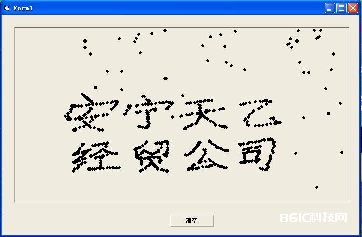
图中的若干零星点是因为硬件并没有做抗搅扰滤波,mcu程序中也没有对接触点进行重复读取所造成的,一般可运用读取两次,重复数据为正确数据的方法来扫除搅扰。

