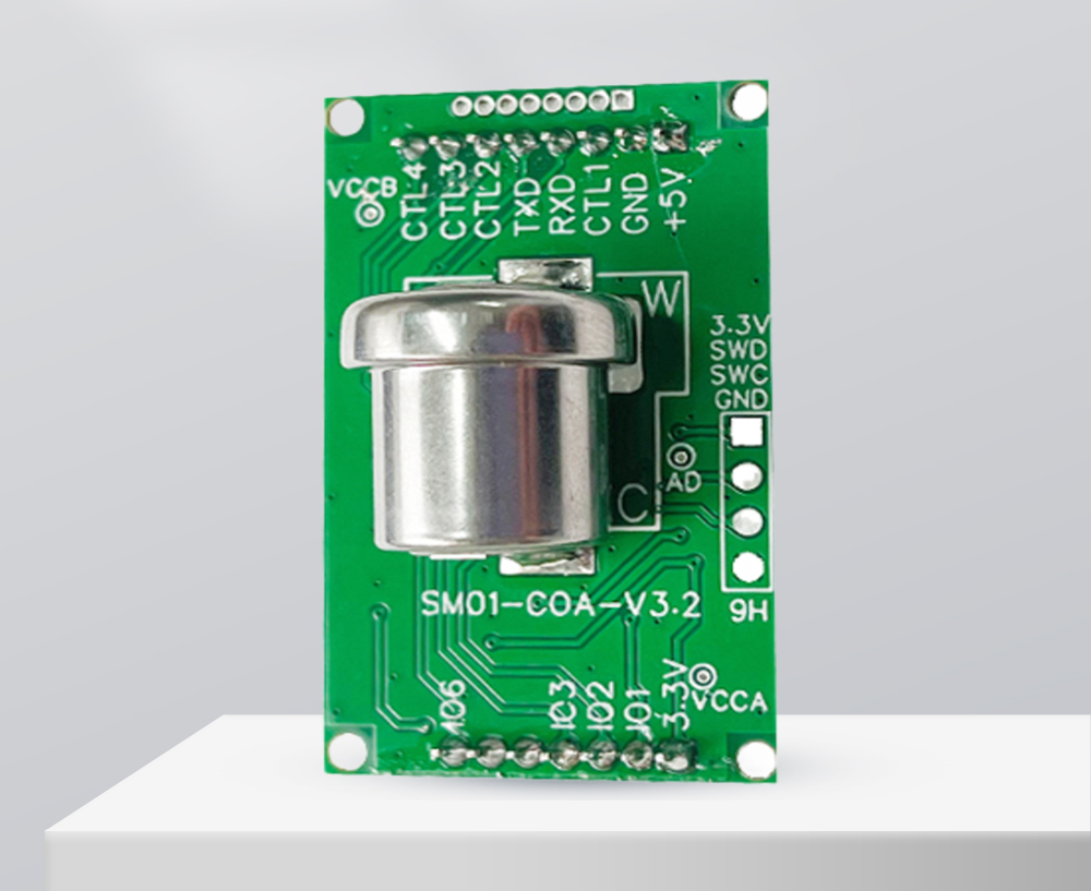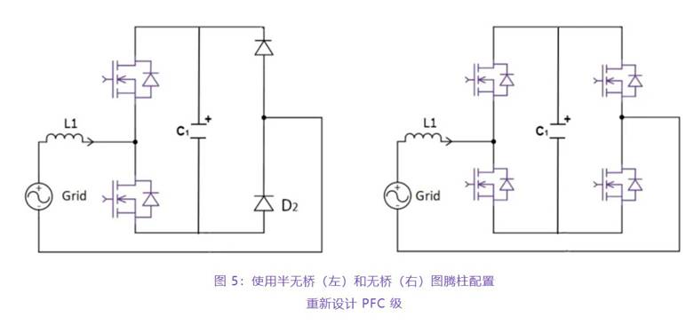
(AM,CD与单片机的P1.3,P1.4的衔接未画出)
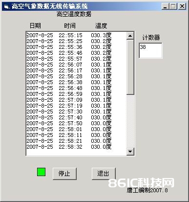
本体系什物相片如下:
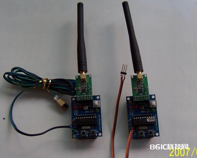
/
#include
#include
#define uchar unsigned char
#define uintunsigned int
#define WC0x00 // Write configuration register command
#define RC0x10 // Read configuration register command
#define WTP0x20 // Write TX Payload command
#define RTP0x21 // Read TX Payload command
#define WTA0x22 // Write TX Address command
#define RTA0x23 // Read TX Address command
#define RRP0x24 // Read RX Payload command
typedef struct RFConfig
{
uchar n;
uchar buf[10];
}RFConfig;
code RFConfig RxTxConf =
{
10,
0x01, 0x0c, 0x44, 0x20, 0x20, 0xcc, 0xcc, 0xcc,0xcc, 0x58
};
// The content of this struct is nRF905s initialize data.初始化数据
// CH_NO=1;433MHZ;Normal Opration,No Retrans;RX,TX Address is 4 Bytes
// RX TX Payload Width is 32 Bytes;Disable Extern Clock;Fosc=16MHZ
// 8 Bits CRC And enable
uchar data TxBuf[32];
uchar data RxBuf[32];
uchar key,rsbrf,delayf,tf;
uchar bdata DATA_BUF;
sbit flag =DATA_BUF^7;
sbit flag1 =DATA_BUF^0;
sbit TX_EN =P1^7;
sbit TRX_CE =P1^6;
sbit PWR_UP =P1^5;
sbit MISO =P1^1;
sbit MOSI =P1^0;
sbit SCK=P3^7;
sbit CSN=P3^3;
sbit AM=P1^3;
sbit DR=P3^2;
sbit CD=P1^4;
sbitLED1 =P3^4;
sbitLED2 =P3^5;
sbitKEY1 =P3^0;
sbitKEY2 =P3^1;
void InitIO(void);// Initialize IO port
void Inituart(void);// initialize 232 uart
void Config905(void);// Config nRF905 module装备NRF905形式
void SetTxMode(void);// Set nRF905 in Tx mode
void SetRxMode(void);// Set nRF905 in Rx mode
void TxPacket(void);// Send data by nRF905
void RxPacket(void);// Recive data by nRF905
void SpiWrite(uchar);// Write data to nRF905
uchar SpiRead(void);// Read data to nRF905
void Delay(uchar n);// Delay 100us
void Scankey(void);// Scan key
void TxData (uchar x);// Send key_value to CRT display
void comdebug(void);
void Delay(uchar n)
{
uint i;
while(n--)
for(i=0;i<80;i++);
}


