什么是FPGA
Xilinx以制作 可编程门阵列(FPGA)而出名,它是依据一个经过可编程接点衔接的可装备逻辑块(CLBs)矩阵。依据Control Engineering Europe中的 “FPGA的长处(Advantages of FPGA)”这篇文章,多种操控回路能够以不同可是十分快的速度在FPGA设备上运转。FPGA也能够在制作后再编程以到达别种运用或是功用需求,这使它在专业工程师中十分盛行。许多工程师都把这种技能运用到机械学习,无线通信,嵌入式视觉和云核算运用中。
什么是ZYNQ
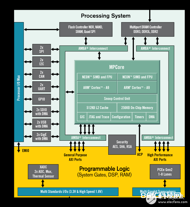
Xilinx Zynq®-7000 全可编程体系芯片 (AP SoC)系列包含了依据嵌入式处理器的软件可编程性和FPGA的硬件可编程性。这个技能使得咱们在单一设备上集成CPU,DSP,ASSP和混合信号功用时进行要害剖析和硬件加速。
装置Vivado, SDK 和板支撑文件
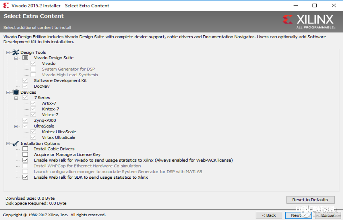
在创立数字或体系规划前你首要需求装置 Xilinx Vivado 规划套件。 Xilinx Vivado Webpack 这个版本是免费的,经过 Digilent Wiki 上供给的运用辅导也能够协助你快读装置和运转Vivado。在下载Vivado时,保证你运用规划东西(Design Tools)栏目中的“软件开发套件(Software Development Kit)”来装置SDK。为了避免你忘了这个过程,你也能够回来装置软件来装置“软件开发套件(Software Development Kit)”。
内容
一旦你下载并装置了Vivado,你需求把ZYBO板文件放入本地Xilinx Vivado文件夹,它界说了ZYBO板上的不同界面和协议。之后你就能够成功树立IP和SDK了。Diligent供给了一个教程: https://reference.digilenTInc.com/reference/software/vivado/board-files?。.. 。
留意:在Vivado board文件装置辅导中,你需求把头文件(board_files)放入你的本地文件夹。然后,我会引荐你仿制独立的board文件(例如,一旦你下载了vivdado board文件,找到vivado-boards-master\new\board_files并仿制“zybo文件夹”。不然你或许会在规划中碰到一些不必要的过错。
创立项目
我将会运用 Digilent ZYBO 并依据他们的 开端攻略(getTIng started guide) 来创立一个简略的HelloWorld项目。
项目概要
在这个项目中你将会学到如何用四个板上的开关来操控板上的LED。当你按下四个不同的按钮后,你能够看到来自电脑端的多种信息。
规划流程
翻开Vivada并挑选Zybo板
创立一个新的Vivado项目
在新的项目中创立一个空的板块规划作业区
运用IP集成东西增加需求的IP模块并创立硬件规划
验证并保存板块规划
创立HDL体系封装
运转规划归纳与完成
生成Bit文件
导出包含了bit源文件的硬件规划到SDK东西
敞开 SDK
硬件规划概要
你能够依据开端攻略(getTIng started guide)中的过程2-6来创立硬件规划,以下是一些阐明。
主动运转模块(Run Block AutomaTIon)对话框能够让你供给微处理器体系需求的一些根底特性输入。
“3.4)双击新的axi_gpio_0内核能够弹出自界说窗口。在IP设置页查看发动双通道,并点击OK”,你能够创立两种输入-SW和BTN。每一个axi_gpio内核都支撑32位单双GPIO通道。在这个项目中,每个通道咱们只需求四位。你能够在AXI GPIO Guide中找到具体信息。
“3.5)重复过程3.3能够增加另一个GPIO内核,可是不要发动双通道”,你将会创立一个输出-LED。
主动运转衔接能够协助你hook界面和外部I/O接口
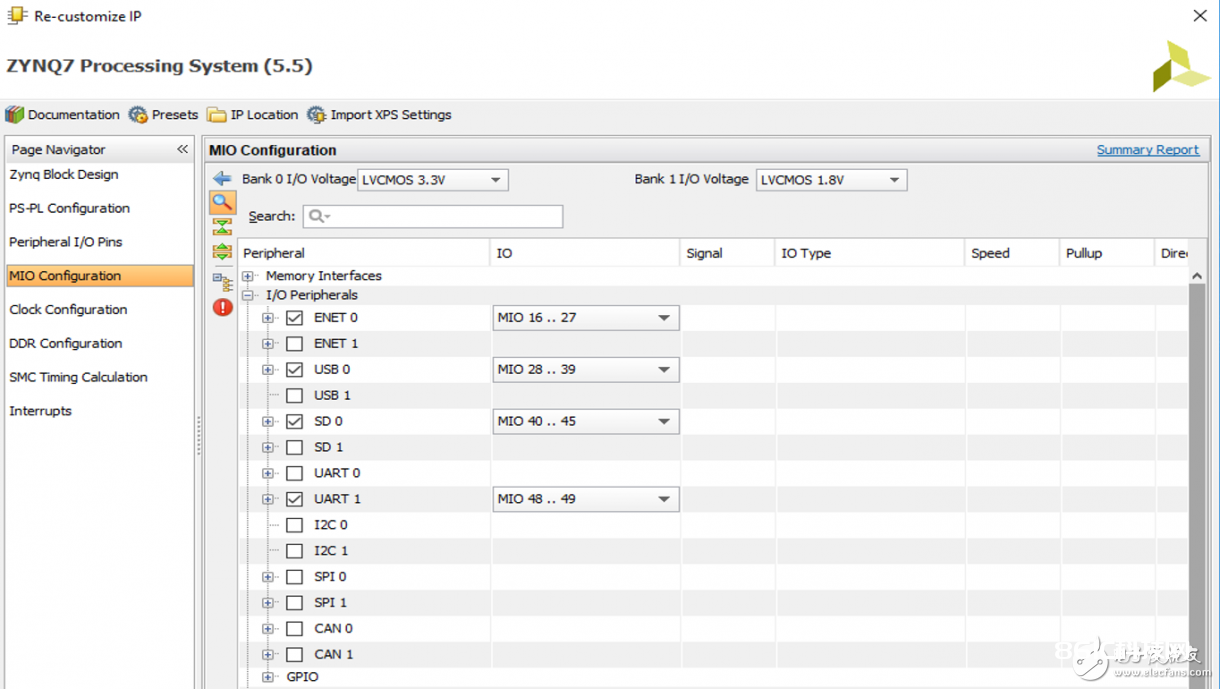
默许,UART界面中的一种现已被放置在ZYNQ IP中了
请参阅:http://blog.dev-flow.com/en/8-first-use-of-the-zynq-7000-processor-system-on-a-zynq/。
软件规划概要
你能够依据开端攻略(getting started guide)中的过程7-10来创立软件规划,以下是一些阐明。
当你翻开“src”文件夹中的“helloworld.c’’文件后(参阅开端攻略(getting started guide)中的过程9.4),你能够经过以下过程在用户界面看到一些预设功用和库的具体内容。
符号功用/库
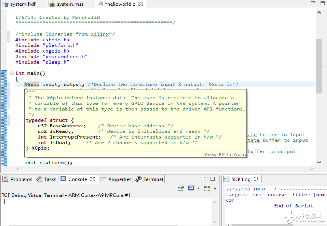
右击预设功用/库并翻开新选项看到声明
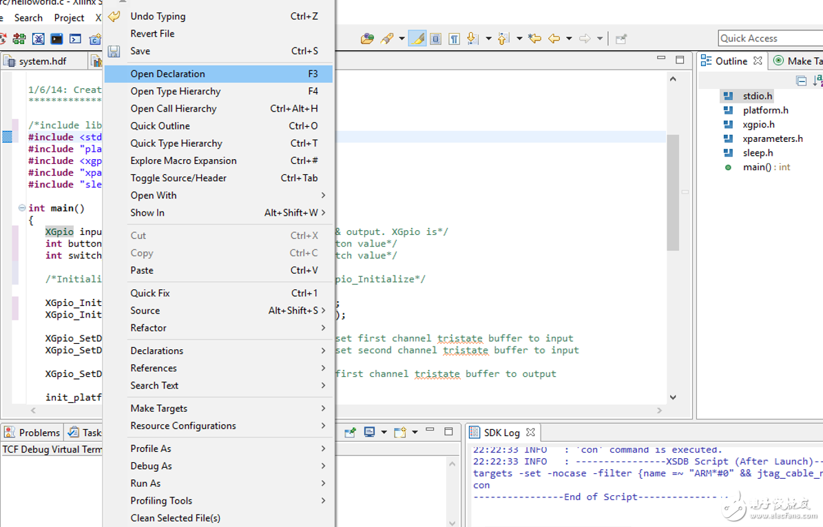
以下是代码和注释
/*****************************************************
Getting Started Guide for Zybo
This demo displays the status of the switches on the
LEDs and prints a message to the serial communication
when a button is pressed.
Terminal Settings:
-Baud: 115200
-Data bits: 8
-Parity: no
-Stop bits: 1
1/6/14: Created by MarshallW
****************************************************/
/*include libraries from Xilinx*/
#include
#include “platform.h”
#include
#include “xparameters.h”
#include “sleep.h”
int main()
{
XGpio input, output; /*Declare two structure input & output. XGpio is*/
int button_data = 0; /*Declare & Define initial button value*/
int switch_data = 0; /*Declare & Define initial switch value*/
/*Initialize the XGpio instance provided by the caller based on the given DeviceID.*/
XGpio_Initialize(&input, XPAR_AXI_GPIO_0_DEVICE_ID); /*We define AXI_GPIO_0 as inputs – BTN & SW*/
XGpio_Initialize(&output, XPAR_AXI_GPIO_1_DEVICE_ID);/*We define AXI_GPIO_1 as inputs – LED*/
XGpio_SetDataDirection(&input, 1, 0xF); /*set first channel of input tristate buffer to input*/
XGpio_SetDataDirection(&input, 2, 0xF); /*set second channel of input tristate buffer to input*/
XGpio_SetDataDirection(&output, 1, 0x0); /*set only channel of output tristate buffer to output*/
init_platform(); /*Initialize the platform hardware resources*/
/*Indefinite loop – running forever*/
while(1){
switch_data = XGpio_DiscreteRead(&input, 2); /*Read the switch (SW) value*/
XGpio_DiscreteWrite(&output, 1, switch_data); /*Write the switch (SW) value to LED (LD)*/
button_data = XGpio_DiscreteRead(&input, 1); /*Read the button (BTN) value*/
/*Set up if-else-if statement to print message in the
*UART terminal. This depends on whether one or
* more buttons are pressed
*/
if(button_data == 0x0){} /*If no button is pressed, do nothing*/
/*If button value is binary 0001 (decimal 1), button 0 (BTN0) is pressed. Use pre-defined function Xil-printf
* to print the message in the terminal
*/
else if(button_data == 0x1)
xil_printf(“button 0 pressed\n\r”);
/*If button value is “binary 0010 (decimal 2)”, button 1 (BTN1) is pressed. Use pre-defined function Xil-printf
*to print the message in the terminal
*/
else if(button_data == 0x2)
xil_printf(“button 1 pressed\n\r”);
/*If button value is “binary 0100 (decimal 4)”, button 2 (BTN2) is pressed. Use pre-defined function Xil-printf
*to print the message in the terminal
*/
else if(button_data == 0x4)
xil_printf(“button 2 pressed\n\r”);
/*If button value is “binary 1000 (decimal 8)”, button 3 (BTN3) is pressed. Use pre-defined function Xil-printf
*to print the message in the terminal
*/
else if(button_data == 0x8)
xil_printf(“button 3 pressed\n\r”);
else
xil_printf(“multiple buttons pressed\n\r”); /*All other values, print “multiple buttons pressed*/
usleep(200000); /*Delay 200000us*/
}
cleanup_platform(); /*Clean up all caches*/
return 0;
}
运转项目
你能够依据过程11来运转项目。在你对FPGA进行编程并成功创立运用后,你能够看到以下:
1. 试着按下四个开关,而且各自相对应的LED会亮起
2. 在串口端,按下每一个按钮,会弹出“按钮已被按下”的信息。


