本例采用了两种方法来输出PWM波形,分别是软件延时法和定时器0,电机驱动芯片是L298,它的中文材料见IC学习笔记。
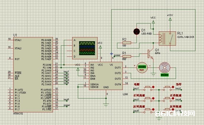
程序代码:
#include
#define uchar unsigned char
#define uint unsigned int
sbit IN1=P2^0;
sbit IN2=P2^1;
sbit key1=P2^3;//电源
sbit key2=P2^4;//急停
sbit key3=P2^5;//正高
sbit key4=P2^6;//正低
sbit key5=P2^7;//反高
sbit key6=P3^4;//反低
sbit power=P3^6;//电源操控
uchar choice=0;
uchar an1=0;
uchar count=0;
void delay1ms(uint z)
{
uint x;
uint y;
for(x=z;x>0;x–)
for(y=122;y>0;y–);
}
void PWMZ()
{
IN1=1;
delay1ms(1);
IN1=0;
delay1ms(2);
}
void PWMF()
{
TR0=1;
while(!TF0);
}
void keyscan()
{
if(key1==0)
{
delay1ms(10);
if(key1==0)
{
while(!key1);
an1++;
if(an1==2) an1=0;
choice=1;
}
}
if(key2==0)
{
delay1ms(10);
if(key2==0)
{
while(!key2);
choice=2;
}
}
if(key3==0)
{
delay1ms(10);
if(key3==0)
{
while(!key3);
choice=3;
}
}
if(key4==0)
{
delay1ms(10);
if(key4==0)
{
while(!key4);
choice=4;
}
}
if(key5==0)
{
delay1ms(10);
if(key5==0)
{
while(!key5);
choice=5;
}
}
if(key6==0)
{
delay1ms(10);
if(key6==0)
{
while(!key6);
choice=6;
}
}
switch(choice)
{
case 1:if(an1) power=1;else power=0;break;
case 2:IN1=0;IN2=0;break;
case 3:IN2=0;IN1=1;break;
case 4:TR0=0;IN2=0;PWMZ();break;
case 5:IN1=0;IN2=1;break;
case 6:IN1=0;PWMF();break;
}
}
void main()
{
power=0;
TMOD=0x01;
TH0=0xff;
TL0=0xff;
ET0=1;
EA=1;
while(1)
{
keyscan();
}
}
void time0() interrupt 1
{
TR0=0;
IN2=~IN2;
if(IN2)//高电平脉宽
{
TH0=0xfc;
TL0=0x18;
}
else//低电平脉宽
{
TH0=0xf4;
TL0=0x48;
}
}
声明:本文内容来自网络转载或用户投稿,文章版权归原作者和原出处所有。文中观点,不代表本站立场。若有侵权请联系本站删除(kf@86ic.com)https://www.86ic.net/bandaoti/fenxiao/260291.html


