A Power Monitor with Improved Response TIme
A selecTIve sampler enables you to sample a signal more quickly and efficiently while retaining the desired frequency resoluTIon. The technique can be used to detect transient power changes rapidly, before blackouts occur.
This arTIcle describes how to sample a signal more quickly and efficiently by using a method of heterodyning (generating new frequencies by mixing or multiplying two oscillating waveforms) over the frequency range of interest. The advantages are that this selective sampling method retains the same frequency resolution as obtained in standard pulse-code modulation (PCM) designs but with a shorter sampling time. In particular, the article shows how to use such a method to detect transient power changes more rapidly.
Time Domain Sampling
Time domain sampling uses an analog-to-digital converter (ADC) that samples an analog signal to convert it to digital format. The sampling frequency of the ADC is chosen to be at least twice the highest frequency in the signal, as the Nyquist theorem requires this to insure that aliasing, or artifacts, are not created. To achieve this, an anti-aliasing filter is placed between the signal and the ADC to attenuate signals that are more than one half the sampling frequency of the ADC.
For example, we will examine a system that samples a signal in the frequency range of 6000–8000 Hz with a desired frequency resolution of 0.5 Hz. Normally, we would sample this signal at 16,000 Hz to satisfy the Nyquist criteria; to achieve 0.5 Hz resolution we would take 32,000 samples (N=32,000, where N is the number of samples), which would typically require 2 s at a 16,000 Hz sampling frequency. Using the proposed method, it is possible to significantly reduce the sampling time to 0.576 s.
Selective Sampling
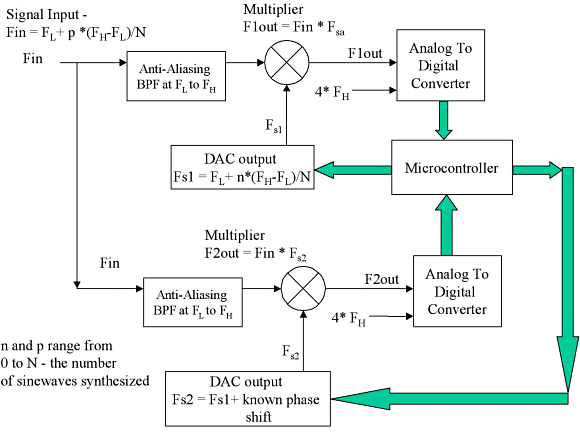
In Figure 1 the incoming signal to be sampled is filtered with a band-pass filter for anti-aliasing. The filter has cut-off frequencies of FL = 6000 Hz and FH = 8000 Hz, where FL and FH are, respectively, the low and high cut-off frequencies. The filtered signal is then sent to two independent multipliers where it is multiplied with synthesized signals from two digital-to-analog converters (DACs). Two more ADCs sample the outputs of the multipliers at a sampling frequency of 4FH. The two separate sets of sampling circuitry are required to find the phase and amplitude components in the spectrum. With twice as many equations that result from two sets of ADC measurements, both phase and amplitude components can be solved simultaneously.
 Figure 1. Design for a selective sampler |


