用c言语写的一个时闹钟程序
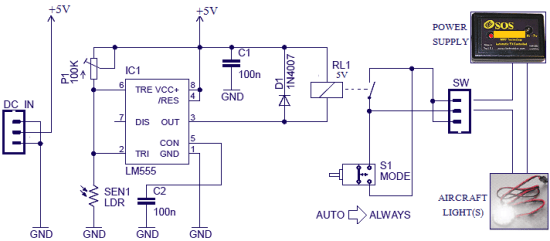
单片机用16F877,主时钟用20MHz,用32768作守时时刻。能够完成2路定闹,每一路都可别离设置和开关,选用4×4键盘,16×2的字符型LCD显现。连线在程序最初有阐明。
程序的功用:
(1)上电后LCD背光翻开,并显现倒计时5秒,然后时钟开端作业。
(2)用形式键(*)切换形式,如显现时刻、日期、闹钟1、闹钟2等,而且能够用上、下键操控加1、减1或是闹钟的On、Off。
(3)原程序有16个键,包含0~9数字键,能够直接输入要设置的时刻值,但后来将数字键撤销了,你依然能够经过修正程序的部分注释康复此功用。
(4)闹钟有2路,时刻到后闹2分钟,可按任意键撤销本次闹钟。闹钟响时有2种腔调,是用PIC的PWM完成的。
(5)按任意键可翻开背光,1分钟后主动封闭背光。
(6)RA0~RA3为按键扫描输入,应接下拉电阻。
主程序
// FileName: Main.c
// MCU: MicroChipPIC16F877
// Tool: CCS-C compiler
// Author: KingEDA, MSN:kingeda@163.com, skype:kingeda, E-mail:kingeda@163.com
// Website:http://www.EDAKING.com
// DescripTIon:
// A TImer program
// Ver 0.1: 2003-03-31, all cLOCk funcTIon with date display, 2 way alarm.
// Ver 0.2: 2003-05-05, (1) Alarm default is on,modify alarm1 TIme to 7:00:00,
// and alarm2 to 13:30:00.
// (2) Backlight will be enabLEDwhen alarming.
// (3) Automatic adjust day(28,30,31)。
// (4) Automatic move cursor to next location when set item.
// PINConnection:
// RC0~1 : 32768Hz crystal
// RC2 : Buzzer
// RC3 : LCD Back Light,drive aPNPBJT
// RD0~RD7 : to LCD DB0~DB7
// RA0~RA3 : keypad col in
// RC4~RC7 : keypad line out
// 7 8 9 #
// 4 5 6 ↑
// 1 2 3 ↓
// 0 ← → *
// RE0 : LCD RS
// RE1 : LCD RW
// RE2 : LCD E
#include “my16f877.h”
#device ICD=true
//#fuses HS,NOWDT,NOPROTECT,PUT,BROWNOUT
#use delay(clock = 24000000)
//#use fast_io(C)
#use fast_io(E)
#define lcd_busy (lcd_read_addr()&0x80) == 0x80
#define time_start_addr 0x80+0x04
#define time_hourh_addr time_start_addr
#define time_hourl_addr time_start_addr+1
#define time_minuteh_addr time_start_addr+3
#define time_minutel_addr time_start_addr+4
#define time_secondh_addr time_start_addr+6
#define time_secondl_addr time_start_addr+7
#define key_0 0x11
#define key_1 0x21
#define key_2 0x22
#define key_3 0x24
#define key_4 0x41
#define key_5 0x42
#define key_6 0x44
#define key_7 0x81
#define key_8 0x82
#define key_9 0x84
#define key_left 0x12
#define key_right 0x14
#define key_up 0x48
#define key_down 0x28
#define key_mode 0x18
#define key_CANcel 0x88
char StrPower1[] = “ *Power on* ”;
char StrSetTime[] = “ * Adjust time* ”;
char StrSetDate[] = “ * Adjust date* ”;
char StrAlarm1[] = “ * Set alarm 1* ”;
char StrAlarm2[] = “ * Set alarm 2* ”;
unsigned char PORTC_MAP;
#bit BackLightEn = PORTC_MAP.3
unsigned char BackLightTimer;
int1 led;
#bit lcd_rs = PORTE.0
#bit lcd_rw = PORTE.1
#bit lcd_e= PORTE.2
#byte lcd_bus = PORTD
#byte lcd_dir = TRISD
#define PWM_on 0x0c
#define PWM_off 0x00
#define PWM_period 200
#define PWM_DC 100
unsigned char lcd_addr;
unsigned char KeyLine;
unsigned char KeyOld;
unsigned char KeyNew;
struct mTime {
unsigned char hourh; // hour,0~23
unsigned char hourl;
unsigned char minuteh; // minute,0~59
unsigned char minutel;
unsigned char secondh; // second,0~59
unsigned char secondl;
};
struct mTime CurrentTime = {1,2,0,0,0,0};
struct mTime AlarmTime1 = {0,7,0,0,0,0}; // 07:00:00
struct mTime AlarmTime2 = {1,3,3,0,0,0}; // 13:30:00
unsigned char AlarmStatus;
#bit Alarm1Enable = AlarmStatus.0
#bit Alarm2Enable = AlarmStatus.1
#bit Alarm1Alarm = AlarmStatus.2
#bit Alarm2Alarm = AlarmStatus.3
unsigned char Alarm1Cnt; // alarm1 second count
unsigned char Alarm2Cnt;
unsigned char CurrentMode;
#define mode_time 0
#define mode_set_time 1
#define mode_set_date 2
#define mode_set_alarm1 3
#define mode_set_alarm2 4
unsigned char adjust_item;
struct mDate {
unsigned char year1; //
unsigned char year2;
unsigned char year3;
unsigned char year4;
unsigned char monthh;
unsigned char monthl;
unsigned char dayh;
unsigned char dayl;
};
struct mDate CurrentDate = {2,0,0,3,0,1,0,1};
unsigned char *pStr;
// ——————————————————-
unsigned char lcd_read_addr()
{
unsigned char ch;
lcd_dir = 0xff; // read from lcd
lcd_rs = 0;
lcd_rw = 1; // inst
lcd_e = 1;
#asm
nop
nop
nop
#endasm
ch = lcd_bus;
lcd_e = 0;
lcd_dir = 0x00; //set write to lcd
return ch;
}
// ——————————————————-
unsigned char lcd_write_data(unsigned char ch)
{
while (lcd_busy)
{ restart_wdt(); }
lcd_rs = 1; // data
lcd_rw = 0; // write
lcd_bus = ch; // write out
lcd_e = 1;
#asm
nop
nop
nop
#endasm
lcd_e = 0;
return ‘Y’;
}
// ——————————————————-
unsigned char lcd_write_inst(unsigned char ch)
{
while (lcd_busy)
{ restart_wdt(); }
lcd_rs = 0; // inst
lcd_rw = 0; // write
lcd_bus = ch;
lcd_e = 1;
#asm
nop
nop
nop
#endasm
lcd_e = 0;
return ‘Y’;
}
// ——————————————————-
unsigned char lcd_read_data()
{
unsigned char ch;
while (lcd_busy)
{ restart_wdt(); }
lcd_dir = 0xff; // read from lcd
lcd_rs = 1; // data
lcd_rw = 1; // read
lcd_e = 1;
#asm
nop
nop
nop
#endasm
ch = lcd_bus; // read in
lcd_e = 0;
lcd_dir = 0x00; //set write to lcd
return ch;
}
// ——————————————————-
void lcd_init()
{
unsigned char Tempch;
lcd_addr = 0;
delay_ms(100);
Tempch = 0x38; // 1-line mode,5×8 dots
lcd_write_inst(Tempch); // Function set
Tempch = 0x0f; // lcd on,cursor on,blink on
lcd_write_inst(Tempch); // Display on/off
Tempch = 0x06; // Increment mode,Entire shift off
lcd_write_inst(Tempch);
Tempch = 0x01; // clear display
lcd_write_inst(Tempch);
delay_ms(3);
}
// ——————————————————-
//#int_timer1
//void timer1_interrupt(void)
#int_ccp2
void ccp2_interrupt(void)
{
//TMR1H = 0x80;
if (CurrentTime.secondl==9)
{
CurrentTime.secondl=0;
if (CurrentTime.secondh==5)
{
CurrentTime.secondh=0;
if (CurrentTime.minutel==9)
{
CurrentTime.minutel=0;
if (CurrentTime.minuteh==5)
{
CurrentTime.minuteh=0;
if (CurrentTime.hourl==9)
{
CurrentTime.hourl=0;
CurrentTime.hourh++;
}
else if((CurrentTime.hourl==3) && (CurrentTime.hourh==2))
{
CurrentTime.hourl=0;
CurrentTime.hourh=0;
if ((((CurrentDate.dayl == 8) || (CurrentDate.dayl == 9)) && (CurrentDate.dayh == 2) && (CurrentDate.monthl == 2) && (CurrentDate.monthh == 0)) ||
((CurrentDate.dayl == 0) && (CurrentDate.dayh == 3) && ((((CurrentDate.monthl == 4) || (CurrentDate.monthl == 6)
|| (CurrentDate.monthl == 9)) && (CurrentDate.monthh == 0)) || ((CurrentDate.monthl == 1) && (CurrentDate.monthh == 1)))) ||
((CurrentDate.dayl == 1) && (CurrentDate.dayh == 3)))
{
CurrentDate.dayl=1;
CurrentDate.dayh=0;
if ((CurrentDate.monthl == 2) && (CurrentDate.monthh == 1))
{
CurrentDate.monthl = 1;
CurrentDate.monthh = 0;
if (CurrentDate.year4 == 9)
{
CurrentDate.year4 = 0;
if (CurrentDate.year3 == 9)
{
CurrentDate.year3 = 0;
if (CurrentDate.year2 == 9)
{
CurrentDate.year2 = 0;
CurrentDate.year1++;
}
else
CurrentDate.year2++;
}
else
CurrentDate.year3++;
}
else
CurrentDate.year4++;
}
else if(CurrentDate.monthl == 9)
{
CurrentDate.monthl = 0;
CurrentDate.monthh++;
}
else
CurrentDate.monthl++;
}
else if(CurrentDate.dayl == 9)
{
CurrentDate.dayl=0;
CurrentDate.dayh++;
}
else
CurrentDate.dayl++;
}
else
CurrentTime.hourl++;
}
else
CurrentTime.minuteh++;
}
else
CurrentTime.minutel++;
}
else
CurrentTime.secondh++;
}
else
CurrentTime.secondl++;
if ((Alarm1Alarm == false) & (Alarm2Alarm == false))
{
led = 0;
CCP1CON = PWM_off;
}
else
{
if (led == 1)
{
led = 0;
PR2 = PWM_period; // set pwm period
CCPR1L = PWM_DC; // set pwm duty cycle
//CCP1CON = PWM_on;
}
else
{
led = 1;
PR2 = PWM_period/2; // set pwm period
CCPR1L = PWM_DC/2; // set pwm duty cycle
//CCP1CON = PWM_off;
}
}
Alarm1Cnt++;
Alarm2Cnt++;
if (BackLightEn == 0)
if (((BackLightTimer++)》=60) & (Alarm1Alarm == false) & (Alarm1Alarm == false))
BackLightEn = 1; // dISAble backlight
PORTC = PORTC_MAP;
//TMR1IF = 0;
//PIR1 = PIR2 = 0x00;
CCP2IF = 0;
}
// ——————————————————-
unsigned char get_key(void)
{
unsigned char key_in,tmp;
TRISC = 0x03;
KeyLine = 0xf0;
PORTC = KeyLine | PORTC_MAP;
#asm
nop
nop
<


