文章转自ADI官网,版权归属原作者一切
Design of the input configuration, or “front end,” ahead of a high-performance analog-to-digital converter (ADC) is critical to achieving desired system performance. Optimizing the overall design depends on many factors, including the nature of the application, system partition, and ADC architecture. The following questions and answers highlight the important practical considerations affecting the design of an ADC front end using amplifier- and transformer circuitry.
Q. What is the fundamental difference between amplifiers and transformers?
A. An amplifier is an active element, while a transformer is passive. Amplifiers, like all active elements, consume power and add noise; transformers consume no power and add negligible noise. Both have dynamic effects to be dealt with.
Q. Why would you use an amplifier?
A. Amplifier performance has fewer limitations than those of transformers. If dc levels must be preserved, an amplifier must be used, because transformers are inherently ac-coupled devices. On the other hand, transformers provide galvanic isolation if needed. Amplifiers provide gain more easily because their output impedance is essentially independent of gain. On the other hand, a transformer’s output impedance increases with the square of the voltage gain—which depends on the turns ratio. Amplifiers provide flatter response in the pass band, free of the ripple due to the parasitic interactions in transformers.
Q. How much noise does an amplifier typically add, and what can I do to reduce this?
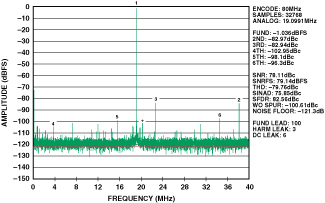
A. A typical amplifier that might be considered, the ADA4937, for example, when configured for G = 1, has an output noise spectral density of 6 nV/rtHz at high frequencies, compared to the 10-nV/rtHz input noise spectral density of the 80-MSPS AD9446-80 ADC. The problem here is that the amplifier has a noise bandwidth equivalent to the full bandwidth of the ADC, around 500 MHz, while the ADC noise is folded to one Nyquist zone (40 MHz). Without a filter, the integrated noise then becomes 155 µV rms for the amplifier and 90 µV rms for the ADC. Theoretically, this degrades the overall system SNR (signal-to-noise ratio) by 6 dB. To confirm this experimentally, the measured SNR, with the ADA4937 driving the AD9446-80, is 76 dBFS, and the noise floor is –118 dB (Figure 1). With a transformer drive, the SNR is 82 dBFS. The driver amplifier has thus degraded the SNR by 6 dB.
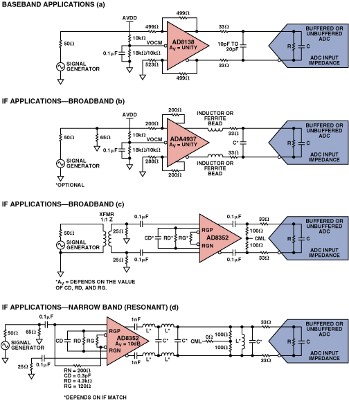
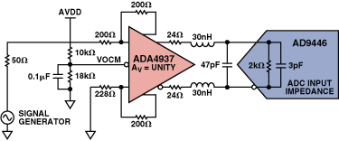
To make better use of the ADC’s SNR, a filter is inserted between the amplifier and ADC. With a 100-MHz 2-pole filter, the amplifier’s integrated noise becomes 71 µV rms, degrading the ADC’s SNR by only 3 dB. Use of the 2-pole filter improves the SNR performance of the Figure 1 circuit to 79 dBFS, with a noise floor of -121 dB, as shown in Figure 2a. The 2-pole filter is built with 24-ohm resistors and 30 nH inductors in series with each of the amplifier’s outputs, and a 47-pF differentially connected capacitor (Figure 2b).
Q. How do high-speed amplifiers and ADCs compare in power consumption?
A. This depends on the amplifier and ADC used. Two typical amplifiers, with similar power consumption, are the AD8352, which draws 37 mA at 5 V (185 mW), and the ADA4937, which draws 40 mA at 5 V (200 mW). Overall power consumption can be reduced by about one-third, with slightly degraded performance, by using a 3.3-V supply. ADCs feature more diversity in power consumption, depending on resolution and speed. The 16-bit, 80-MSPS AD9446‑80 draws 2.4 W, the 14-bit, 125-MSPS AD9246-125 draws 415 mW, and the 12-bit, 20-MSPS AD9235-20 draws only 95 mW.
Q. When do you need to use a transformer?
A. Transformers offer the biggest performance advantage compared to amplifiers at very high signal frequencies and when significant additional noise cannot be tolerated at the ADC input.
Q. How do transformers and amplifiers differ when providing gain?
A. The main difference is in the impedance they present to the ADC input, which directly affects system bandwidth. A transformer’s input- and output impedance are related by the square of the turns ratio, while an amplifier’s input and output impedance are essentially independent of gain.
For example, when a G = 2 transformer is used from a 50-ohm source impedance, the impedance seen at the secondary side of the transformer is 200 ohm. The AD9246 ADC has a differential input capacitance of 4 pF which, coupled with the 200-ohm transformer impedance, reduces the ADC’s –3-dB bandwidth from 650 MHz to 200 MHz. Extra series resistance and differential capacitance are often needed to improve performance and reduce kickback from the converter, which can limit –3-dB bandwidth further, possibly to 100 MHz.
When a low-output-impedance amplifier—such as the ADA4937—is used, the result is a very low source impedance, usually less than 5 ohm. 25-ohm transient-limiting resistors can be used in series with each ADC input; in the case of the AD9246, the ADC’s full 650-MHz analog input bandwidth would be usable.
So far the discussion has been about –3-dB bandwidths. When tighter flatness is needed, say 0.5 dB in a 1-pole system, the −3-dB bandwidth needs to be about 3× wider. For 0.1-dB flatness with one pole, the ratio increases to 6.5×. If 0.5‑dB flatness is required at up to 150 MHz, a –3-dB bandwidth greater than 450 MHz is required, which is difficult to attain with a G = 2 transformer but is straightforward with a low-output-impedance amplifier.
Q. What are the factors to consider in choosing a transformer or an amplifier to drive an ADC?
A. They can be boiled down to a half-dozen parameters—outlined in this table:
| Parameter | Usual preference |
| Bandwidth | Transformer |
| Gain | Amplifier |
| Pass band flatness | Amplifier |
| Power Requirement | Transformer |
| Noise | Transformer |
| DC vs. ac coupling |
Amplifier (dc level preservation)
声明:本文内容来自网络转载或用户投稿,文章版权归原作者和原出处所有。文中观点,不代表本站立场。若有侵权请联系本站删除(kf@86ic.com)https://www.86ic.net/qiche/dianzi/44421.html
|


