学习STM32时,首要要了解流水灯例程,在这里就来剖析流水灯中的GPIO_Init()函数
例如:流水灯例程中运用的端口是macLED1_GPIO_PORT=GPIOB,
操控的引脚是GPIO_Pin_0,
引脚的形式是GPIO_Mode_Out_PP(通用推挽输出),
引脚的速率是GPIO_Speed_50MHz,
用到的寄存器是CRL
将上述的引脚、形式、速率换算成32位的16进制,分别是:
1)操控的引脚是GPIO_Pin_0
换算成32位的16进制是:0x0000 0001
2)引脚的形式是GPIO_Mode_Out_PP(通用推挽输出)
换算成32位的16进制是:0x0000 0010
3)引脚的速率是GPIO_Speed_50MHz
换算成32位的16进制是:0x0000 0003
然后调用库函数GPIO_Init(),初始化GPIOB
GPIO_Init(macLED1_GPIO_PORT, &GPIO_InitStructure);
GPIO_Init()函数的界说如下:

GPIO Mode ConfiguraTIon
currentmode=((uint32_t)GPIO_InitStruct-》GPIO_Mode)&((uint32_t)0x0F);
能够得出currentmode=0x0000 0010 & 0x0000 000F
=0x0000 0000
if ((((uint32_t)GPIO_InitStruct-》GPIO_Mode) & ((uint32_t)0x10)) != 0x00)
判别是否是输出形式,“是”,履行下面代码;“否”,不履行
如:0x0000 0010 & 0x0000 00010 !=0x 0000 0000
则履行下面句子
{
/* Output mode */
currentmode “= (uint32_t)GPIO_InitStruct-》GPIO_Speed;
能够得出currentmode=currentmode | 0x0000 0003=0x0000 0000
=0x0000 0003
}
GPIO CRL ConfiguraTIon
if(((uint32_t)GPIO_InitStruct-》GPIO_Pin&((uint32_t)0x00FF)) != 0x00)
判别是否是Pin0~Pin7引脚,“是”,履行下面代码;“否”,不履行
如:0x0000 0001 & 0x 0000 00FF != 0x0000 0000
则履行下面句子
{
tmpreg = GPIOx-》CRL;
备份原CRL寄存器的值
则是:tmpreg=0x4444 4444
for (pinpos = 0x00; pinpos 《 0x08; pinpos++)
{
pos = ((uint32_t)0x01) 《《 pinpos;
pos是0x0000 0001左移 pinpos 位得到的
如:pos=0x0000 0001 《《 0x00
= 0x0000 0001
为后边的if (currentpin == pos) 判别作预备
/* Get the port pins posiTIon */
currentpin = (GPIO_InitStruct-》GPIO_Pin) & pos;
可得currentpin= 0x0000 0001 & 0x0000 0001
=0x0000 0001
为后边的if (currentpin == pos) 判别作预备
if (currentpin == pos)
由上面得出的pos = 0x0000 0001
currentpin = 0x0000 0001
两者持平,则履行下面代码句子
{
pos = pinpos 《《 2;
可得pos= 0x0000 0000 《《 2
=0x 0000 0000
/* Clear the corresponding low control register bits */
pinmask = ((uint32_t)0x0F) 《《 pos;
可得pinmask=0x0000 000F 《《 0x0000 0000
= 0x0000 000F
tmpreg &= ~pinmask;
可得tmpreg= tmpreg & ~pinmask
= 0x4444 4444 & 0xFFFF FFF0
= 0x4444 4440
/* Write the mode configuraTIon in the corresponding bits */
tmpreg |= (currentmode 《《 pos);
首要,要知道currentmode 《《 pos = 0x0000 0003 《《 0x 0000 0000
= 0x 0000 0003
可得tmpreg= tmpreg | 0x0000 0003
= 0x4444 4440 & 0x0000 0003
= 0x4444 4443
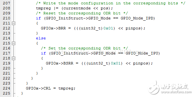
/* Reset the corresponding ODR bit */
if (GPIO_InitStruct-》GPIO_Mode == GPIO_Mode_IPD)
判别是否为下拉输入形式
{
GPIOx-》BRR = (((uint32_t)0x01) 《《 pinpos);
}
else
{
/* Set the corresponding ODR bit */
if (GPIO_InitStruct-》GPIO_Mode == GPIO_Mode_IPU)
判别是否为上拉输入形式
{
GPIOx-》BSRR = (((uint32_t)0x01) 《《 pinpos);
}
}
成果,两种输入形式都不是,而是通用推挽输出,所以不履行
}
}
GPIOx-》CRL = tmpreg;
把前面处理后的暂存值写入到CRL寄存器之中
也便是GPIOx-》CRL= 0x4444 4443
}
终究,向GPIOB组的CRL寄存器写入一个值:
GPIOx-》CRL = 0x4444 4443
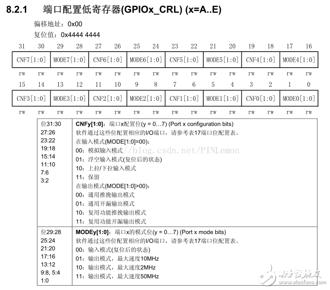
转换为二进制是:(0100 0100 0100 0100 0100 0100 0100 0011)B
因而,Pin0的操控值为(0011)B
下面是CRL寄存器的阐明

比照一下CRL寄存器的阐明,Pin0的操控值正好能够把GPIO设置为契合咱们输入参数要求的状况,即最大速率为50MHz的通用推挽输出形式。


