根本特色:
DS28EA00数字温度传感器是具有9位(0.5℃)至12位(1/16℃)分辨率和用户可编程非易失性(NV)上、下触发点报警功用的数字温度计。每个DS28EA00都具工厂编程的仅有64位序列号。通讯时只需一根数据线和地线,就可经过1-Wire?协议串行传输数据。改进型1-Wire接口具有滞回和搅扰滤波功用,使得DS28EA00可以在大的1-Wire网络中牢靠作业。与其他1-Wire温度计不同,DS28EA00具有两个额定的引脚用以履行次序检测功用。该特性答运用户将器材在链路中的物理方位与序列号对应,例如,用来丈量贮存塔不同高度处的温度。假如无需次序检测功用,这些引脚可作为通用输入或输出。DS28EA00可以直接从数据线获取电源进行作业(寄生供电),因而无需外部电源。
·数字温度计丈量规模:-40℃至+85℃
·用户可选择的9至12位温度分辨率
·共同的1-Wire接口,仅需单个引脚即可进行通讯
·每个器材都具有在工厂激光刻蚀的仅有64位序列号
·ROM多节点才能简化分布式温度检测运用
·具有滞回和搅扰滤波器的改进型1-Wire接口
·用户可定义的非易失性(NV)报警温度设置/用户字节
·报警查找指令可以快速确认温度超出设定规模的器材
·规范和高速1-Wire通讯形式
·2个通用可编程IO (PIO)引脚
·级联功用运用PIO引脚检测器材在网络中的物理次序
·作业规模:3.0V至5.5V,-40℃至+85℃
·可由数据线供电
计划特色
The DS28EA00 evaluation system (EV system) consists of a single evaluation kit (EV kit) that includes an evaluation board (EV board) made up of three subsections that can be broken/snapped off into three independently exercisable boards. Since one of the major features of the DS28EA00 is detection of physical sequence, a block of dip switches are provided on each subsection of the EV board to re-order the physical connection between the chips. Optionally, the customer can break off the subsections of the eval board, connect them together with the provided cables, and re-order the physical sequence of the DS28EA00s that way.
Easy Setup
Stand-Alone EV Board
Contains Three Separate, Breakable Subsections with a DS28EA00 Per Subsection
The Dipswitch Block on Each EV Board Subsection Routes Physical Chain-Mode
Connections Between Chips When Used as a Stand-Alone Board
EV Board’s Subsections are Breakable Into Three Separate Boards Each of Which Evaluates a Single DS28EA00 or, When Cabled Together, Evaluate Chain-Mode Searching
LEDs Give Visual Indicators of PIO Activity
6-Pin Terminal Strip Allows PIO Testing Outside of Chain Mode
PC Connectivity Included
RoHS Compliant
Free Downloadable Evaluation Software Available
参阅原理图
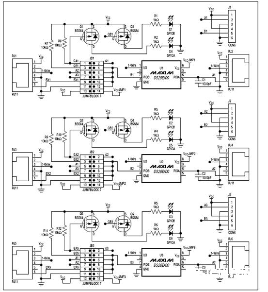
图1 参阅原理图
参阅pcb图
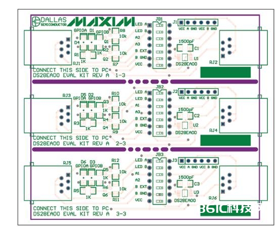
图2 参阅layout top
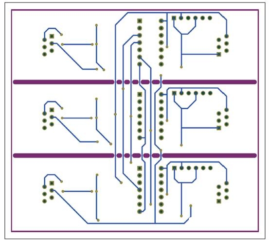
图3 参阅layout bottom
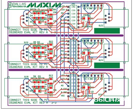
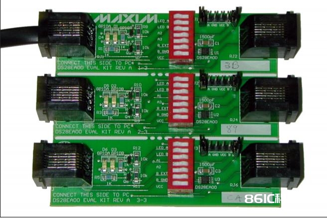
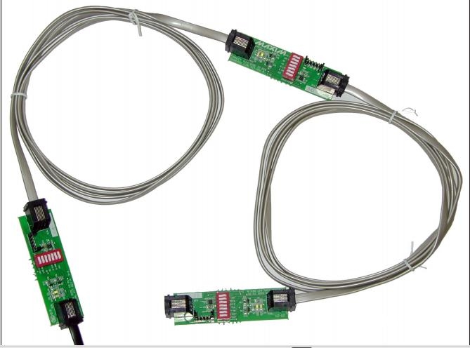
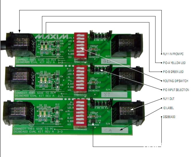
图4: 参阅layout composite


