1.整体规划计划
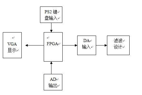
1.1 主操控模块
计划一:选用单片机。单片机的运用较为广泛,可是单片机的处理频率达不到咱们的要求。所以咱们只能够运用处理速度较快的处理器。
计划二:选用Xilinx的FPGA来完结主操控器。Xilinx的FPGA的内部IP核能够便利的发生DDS波形,这样就便利咱们能够更好的发生想要的波形。
所以选用计划二。
1.2显现模块
计划一:运用TFT触摸屏。彩屏有这样显着的长处:微功耗,尺度小,超薄轻盈,显现信息量大,笔迹漂亮,视觉舒适,可是关于FPGA来说,其完结对触摸屏的操控不能够较好的完结操控要求。
计划二:运用VGA显现。FPGA能够完结对VGA的操控。VGA的运用较为广泛,且价格在接纳的规模之内。而且,关于FPGA来说,完结对VGA接口的操控比操控其他的显现器愈加的便利和方便。这就节省了咱们的规划费事。
所以选用计划二。

1.3 输入模块
计划一:运用矩阵键盘。矩阵键盘的编码较为简答,且能够完结较为杂乱的操控。可是矩阵键盘的按键过少,不能够完结更多数据的输入。
计划二:运用PS2键盘。PS2键盘的操控更为简略,咱们能够经过两根数据线精心数据的读取,且PS2键盘的规划愈加契合咱们规划要求,这就决议了PS2在本规划中的优势。
故选用计划二。

1.4 AD输出模块
ADS7822是一种单片高速12位逐次比较型A/D转化器, ADS7822内置双极性电路构成的混合集成转化显片,具有外接元件少,功耗低,精度高级特色,而且具有主动校零和主动极性转化功用,只需外接少数的阻容件即可构成一个完好的A/D转化器。所以该计划选用ADS7822作为AD输入的%&&&&&%。

1.5 DA输出模块
DAC7513是8分辨率的D/A转化集成芯片。与微处理器彻底兼容。这个DA芯片以其价格低廉、接口简略、转化操控简单等长处,在单片机运用体系中得到广泛的运用。D/A转化器由8位输入锁存器、8位DAC寄存器、8位D/A转化电路及转化操控电路构成。

2.程序规划
2.1 AD输出

–**********************分频进程*************************
process(clk)
variable cnt1 : integer range 0 to 100;
variable cnt2 : integer range 0 to 20;
begin
if clkevent and clk=1 then
if cnt1=100 then
cnt1:=0;
if cnt2=20 then
cnt2:=0;
clock=not clock;
if(cnt=3)then
cnt=0;
else
cnt=cnt+1;
end if;
else
cnt2:=cnt2+1;
end if;
else
cnt1:=cnt1+1;
end if;
end if;
end process;
–**************状况驱动进程**********************
sync :process(clock,reset)
begin
if(reset = 0) then
current_state = start;
elsif(clockevent and clock=1) then
current_state = next_state;
end if;
end process sync;
–***************adc驱动进程*******************
comb :process(current_state, intr)
begin
case current_state is
when start => –发动状况
next_state = convert;
cs = 0;
wr = 0;
rd = 1;
read_data = 0;
when convert =>–初始化
if(intr = 0) then
next_state = read1;
else
next_state = convert;
end if;
cs = 1;
wr = 1;
rd = 1;
read_data = 0;
when read1 =>–读状况1
next_state = read2;
cs = 0;
wr = 1;
rd = 0;
read_data = 1;
when read2 =>–读状况2
next_state = start;
cs = 1;
wr = 1;
rd = 1;
read_data = 0;
when others =>–其他状况
next_state = start;
end case;
end process comb;
–****************读取AD数据********************
get_data: process(clock,reset)
begin
if(reset = 0) then
p=0;
elsif(clockevent and clock=1) then
if(read_data = 1) then
p=conv_integer(data_i);
end if;
end if;
end process;
2.2 DA输出

–*********************65536Hz分频进程************************
process(clk)
variable cnt1 : integer range 0 to 762;
begin
if clkevent and clk=1 then
case cnt1 IS
WHEN 381 =>
cp_65k=1;
cnt1:=cnt1+1;
WHEN 762=>
cnt1:=0;
cp_65k=0;
cp_wr=0;
WHEN 20=>
cp_wr=1;
cnt1:=cnt1+1;
WHEN OTHERS=>
cnt1:=cnt1+1;
end case;
end if;
end process;
–*********************1kHz分频进程************************
process(cp_65k)
variable cnt1 : integer range 0 to 64;
begin
if cp_65kevent and cp_65k=1 then
case cnt1 is
when 32=>cp_1k=1;
cnt1:=cnt1+1;
when 64=>cnt1:=0;
cp_1k=0;
when others=>cnt1:=cnt1+1;
end case;
end if;
end process;
–**************DDS地址累加器进程**********************
PROCESS(cp_65k)
BEGIN
IF(cp_65kEVENT AND cp_65k=1) THEN
–DDS累加器循环累加dds_m
IF dds_add65535 THEN
dds_add=dds_add+dds_m;
ELSE
dds_add=dds_add+dds_m-65536;
END IF;
END IF;
END PROCESS;
–***********************频率加减操控进程***************************
process(cp_1k)
VARIABLE keys:INTEGER RANGE 0 TO 127 :=0; –消抖累加器
begin
if cp_1k=1 then
case key is
when 10=> –频率加
if keys=127 then
keys:=0;
bell=1;
if dds_m=1000 then
dds_m=1;
else
dds_m=dds_m+1;
end if;
else
keys:=keys+1;
end if;
when 01=> –频率减
if keys=127 then
keys:=0;
bell=1;
if dds_m=1000 then
dds_m=1;
else
dds_m=dds_m-1;
end if;
else
keys:=keys+1;
end if;
when others=>bell=0;
end case;
end if;
end process;
end dac;
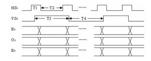
2.3 VGA显现
3.性能指标

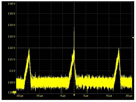
DA输出的波形
4.总结
经过了多日的尽力,咱们在本规划中根本完结了上述要求,并在有些功用方面提出了改善,使体系规划愈加完善。在该规划中咱们运用了FPGA作为主控器,但由于时刻及器件条件的约束,本规划也存在缺乏,例如,丈量规模不能到达更高的要求,丈量精度也存在很大的提高空间。咱们会在今后的学习中不断地补偿这些缺乏,完善丈量体系规划。


